North Texas QRP Kits
ACCUPROBE KIT
Description
Circuit design by Joe,
N2CX,
the Accuprobe is
a descendant of the common diode RF detector.
It uses a special operational amplifier with a compensation diode to
cancel out non-linear diode characteristics at low RF input levels.
This allows accurate measurements down to about 50 mV rms as compared to
several volts for ordinary detectors. This
translates to a very low QRpp level of about 50 microwatts.
The upper end of the range is 5 V rms or 1/2 watt.
A second uncompensated range is provided to allow measurements up to 35 V
rms or 24-1/2 watts. Compensation is
not needed for the higher voltage range since the detector is linear for high
input levels.
The Accuprobe is
used as an accessory to a reasonable quality digital multimeter. It
provides a DC output voltage that gives a DMM reading calibrated to the RMS
value of the Accuprobe RF input. On
the LOW range the DC is read directly while the DMM reading is 1/10 the RF input
on the HIGH range.
The Accuprobe is
AC coupled so it can be connected directly to biased circuits with voltages up
to 50V without upsetting circuit bias or inaccurate readings due to presence of
DC. Its high input impedance and low
capacitance allow it to be used with minimum loading on high impedance low-level
circuits.
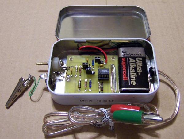
A unique housing
method will be described to allow the builder to construct a self-contained
shielded detector with a built-in probe and convenient ground lead.
Hints for improving performance and tailoring the detector for other uses
will be given later for the advanced homebrewer.
Usage
The Accuprobe is
useful for measuring RF signals with predictable results from 100 kHz to at
least 30 MHz at levels ranging from 10’s of millivolts up to 35 V rms.
It provides minimal circuit loading so that it can be used for signal
tracing in oscillator and mixer circuits as well as multistage QRP transmitters.
Several suggested applications are:
·
Amplifier input and output
voltages to determine gain
·
Filter input and output voltages
to determine loss
·
Measurement of resonant circuit or
filter circuits across a frequency band to check bandwidth or Q
·
RF power levels across a dummy
load from microwatts to beyond QRP. Note
that a very accurate 50 ohm dummy load is needed to retain accuracy.
·
Attenuator calibration by accurate
loss measurements.
·
Signal generator output
calibration
The
Accuprobe circuit board can also be incorporated into other projects wherever
accurate repeatable RF voltage measurements are needed
Specifications:
- Printed circuit board dimensions: 1.8X1.9 inches
- Power: 9 VDC at approx 1 ma using a standard 9-volt battery
- Input levels: LOW range - 50 mV rms to 5V rms (usable to 20 mV)
HIGH range – 5 V rms to 35 V rms
- Frequency range: 100 kHz to 30 MHz (Upper end not tested but should extend to VHF)
- Outputs : DC-compensated to rms input
- LOW range – 50 mV DC to 5 VDC (Uncalibrated readings to 20 mV)
- HIGH range – 5 VDC to 35 VDC (1/10 RMS input)
- Output accuracy: approx. 10% of reading decreasing to 25% at 50mv
What you get: You will receive the
PC board, all board mounted parts and link to the instruction / operation manual. The
builder will need to provide the enclosure and battery.
Price: $ 20.00 + $3.00
shipping to any
location in the USA.
Availability:
VERY LIMITED AT THIS TIME - PLEASE ASK
BEFORE PAYPALing
Ordering Instructions :
CHECK with me FIRST!!!
We accept
PayPal to KK5NA @ kk5na.com,
or
check, M.O. or cash to Joe Spencer 1501 W.
Division St., Arlington, TX 76012
Thanks!
Be sure to include:
Your Name
Address
and email address (If you have one)
|
email: kk5na @ kk5na.com |
Documentation : The latest
revision of the kits' Instruction
and Operation Manual are
available here. Windows users can right click on the manual and choose
"Save Target As..." to download.
Credits
The Accuprobe project:
Printed circuit layout has been redone by Rex, W1REX.
Circuit design was by Joe, N2CX.